Welcome to HDLBits-Verilog-Solutions!
---------------------------------------------------------------------------
Question 3: Create a module with one input and one output that behaves like a wire.
Unlike physical wires, wires (and other signals) in Verilog are directional. This means information flows in only one direction, from (usually one) source to the sinks (The source is also often called a driver that drives a value onto a wire). In a Verilog "continuous assignment" (assign left_side = right_side;), the value of the signal on the right side is driven onto the wire on the left side. The assignment is "continuous" because the assignment continues all the time even if the right side's value changes. A continuous assignment is not a one-time event.
The ports on a module also have a direction (usually input or output). An input port is driven by something from outside the module, while an output port drives something outside. When viewed from inside the module, an input port is a driver or source, while an output port is a sink.
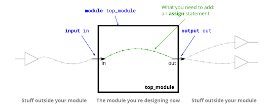
The diagram below illustrates how each part of the circuit corresponds to each bit of Verilog code. The module and port declarations create the black portions of the circuit. Your task is to create a wire (in green) by adding an assign statement to connect in to out. The parts outside the box are not your concern, but you should know that your circuit is tested by connecting signals from our test harness to the ports on your top_module.
 |
| Fig 3.1 |
Solution:
module top_module( input in, output out );
assign out=in;
endmodule
---------------------------------------------------------------------------
Thank you!!!!