Sunday 30 January 2022

Analysis of n-MOSFET using Cadence Virtuoso

 In this blog we will see how to perform Analysis of n-MOSFET on Cadence Virtuoso,

Steps to perform a Analysis of n-MOSFET are as follows:

1. Go to Instance --> browse --> gpdk180 --> nmos --> symbol --> close --> hide

2. Again Instance --> browse --> analogLib --> vdc -->symbol --> close --> hide

3. Do wiring in circuit and add "gnd"

4. In the properties of both voltage source V1 and V2, in DC voltage name them as V1 as "vgs" and V2 as "vds"

5. Click on "check and save", if shows error then correct it.

6. Launch --> ADEL


7. Right click --> copy from cellview

8. Give value as 0.8 to both vgs and vds respectively

9. Analyses --> DC --> "save dc operating point" --> design variable --> select "vgs" for transfer characteristics --> range 0 to 1.4

10. Outputs --> "To be plotted" --> select the upper terminal of nmos for "Id"

11. RUN

Now, for Output characteristics of n-MOSFET

12. Go to Analyses --> choose --> change variable "vgs" to "vds"

13. RUN


I hope this will help you, if want to know more about cadence then you can visit,

Playlist: https://youtube.com/playlist?list=PLrwRwVZrfkcratatpzgtALFDhgcq9hCs8

Thanks...

Saturday 29 January 2022

Verification of Characteristics of Diode using Cadence Virtuoso

 In this blog we will see how to perform Characteristics of Diode on Cadence Virtuoso,

1. Forward Bias

2. Reverse Bias

Steps:

1. Create instance by selecting “create instance” command or by pressing “I” on keyboard.

2. For diode, lib -> gpdk180, cell -> ndio, select “symbol” -> close -> hide

3. For resistance, lib -> analogLib, cell -> res, select “symbol” -> close -> hide

4. For ground, lib -> analogLib, cell -> gnd, select “symbol” -> close -> hide

5. For dc voltage, lib -> analogLib, cell -> vdc, select “symbol” -> close -> hide

6. Change properties of component by pressing key “q” after selecting that component.

7. Dc voltage = Vd, i.e. Vdc=Vd

8. check and save or “ctrl+S”

9. launch -> ADE L {Analog Design Environment Launch}

10. setup -> modal libraries -> select correct path of your schematic if not selected.

11.  Design variables -> Vd -> 1

12. Analyses -> choose


Here set values according to condition that whether it is forward bias or reverse bias. Above example is for reverse bias.

For forward bias start->0 and stop->+1.8

Step size-> 0.1 or no. of steps as 20


13. Variables -> copy from cellview

14. Output -> plotted from cellview ->select from schematic -> select a terminal point of diode where you want to find a V-I characteristics.

15. Click on Netlist and Run.

Thanks....

Use of Tools in Cadence Virtuoso

Cadence Virtuoso helps in making integrated circuit design.... Cadence Virtuoso provides various features. It has very useful tools.

To know the use of tools and commands in cadence virtuoso watch the embedded video given below:


YouTube Channel Link: https://www.youtube.com/channel/UCX4XuMGYu8ksAO4Nnia1umQ

Thanks...

Thursday 27 January 2022

How to create Library and Cellview in Cadence Virtuoso ?....

 In this tutorial, we will see how to create Library and Cellview in Cadence Virtuoso. I will mention only the steps here, if you want to see this process in detail then you can prefer the following link,

Link: https://youtu.be/lAlEWwCzrvU


*****Steps for creating Library and Cellview in Cadence Virtuoso:*****

1. Open Cadence Virtuoso.

2. Click on Virtuoso Dialog Box.

3. Click on File.

4. Click on New à Library à give name to library.

5. While making library make sure to select “Attach to an existing Library” à click “OK” à select “gpdk180” as technology.

6. “gpdk180” is simply a library in which certain rules a defined according to requirements of semiconductors for certification of schematic design of circuit.

7. Click “OK”.

8. Now, again click on Virtuoso dialog box à File à “Cellview”.

9. Give name to “Cellview” under the “Library” which you have made.

10. Click “OK”.

11. Now, schematic window will open.


YouTube Video:


Thanks...


Cadence Virtuoso

 Cadence Virtuoso

Cadence Virtuoso is a software used to make electronic circuits. This software helps in doing various analysis of circuit. Cadence Virtuoso Software is basically used to make electronic circuits for fabrication process. 

The Cadence Virtuoso System Design Platform links two world-class Cadence technologies—custom IC design and package/PCB design/analysis—creating a holistic methodology that automates and streamlines the design and verification flow for multi-die heterogeneous systems.

The Virtuoso System Design Platform allows IC designers to easily include system-level layout parasitics in the IC verification flow, enabling time savings by combining package/board layout connectivity data with the IC layout parasitic electrical model. The automatically generated “system-aware” schematic that results can then be easily used to create a testbench for final circuit-level simulation. The Virtuoso System Design Platform automates this entire flow, eliminating the highly manual and error-prone process of integrating system-level layout parasitic models back into the IC designer’s flow.


Above Image shows the analysis that you can do using Cadence Virtuoso. You can also do other analysis like Paramatric Analysis, also can use calculator to check graphical representation manually.

Hope so, that all of you are reading this Blog will understand the need of Cadence Virtuoso.
Thanks....

Latest

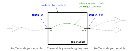
Question 3: Wire {HDLBits-Verilog-Solutions}

  Welcome to  HDLBits -Verilog-Solutions ! --------------------------------------------------------------------------- Question 3:   Create ...

Popular Posts